


10Pcs MAX7219 Dot Matrix Module Microcontroller LED Module Display Module MAX7219 DIY Kit
213

 Direct purchase from the factory
Suroxit Rupantor

 Moffat Dhod
 Poth Prokria
 Parthonn Prokria
Moffat Dhod
Roymall-ak Swagat, Tumche Dhod Store. Ami Tumche Avodd Pasun Moffat Dhod Ditat. Amche Dhod Sod ani Tumcho Dhod Ghe.Poth Prokria
Amchem Poth 2 Disam Bhitor.Normal Poth 5-7 Disam.Poth Kal Videshanchea Vellar Bodol Zait.1. Parthonn Prokria
Amkam roymall.com pasun Kinnnlelem Parthonn Ghetat. Moffat Dhod Parthonn Zainat. Dhod Upayog Zainaslem Parthonn Ghetat.Parthonn 3-5 Disam Bhitor Ghetat.Pasun Dhod Parthonn Zainat.Amkam Email: service@roymall.com va Whatsapp: +86193598494712.Rupantor
Parthonn Zalem Porthun Rupam Miletat. Poth Kharch Parthonn Zainat.Amkam Email: service@roymall.com va Whatsapp: +8619359849471
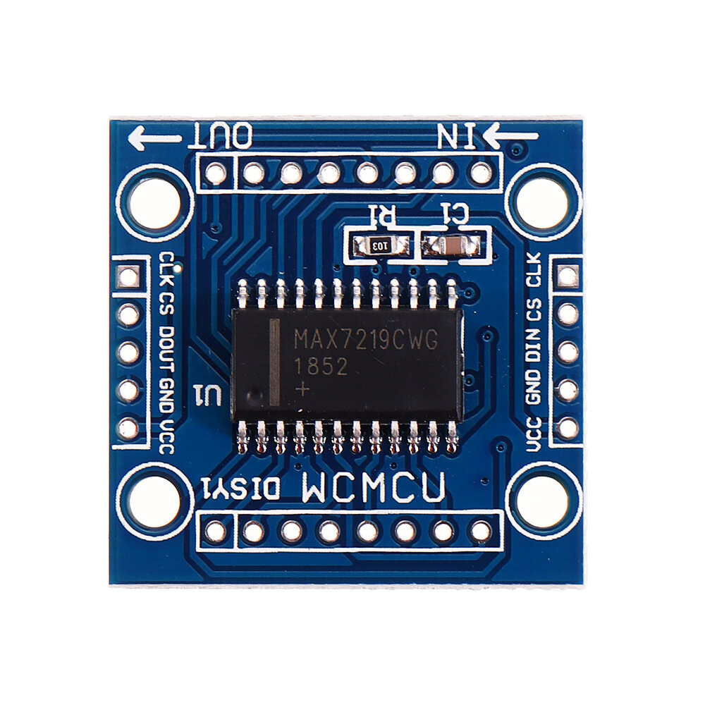
Description:
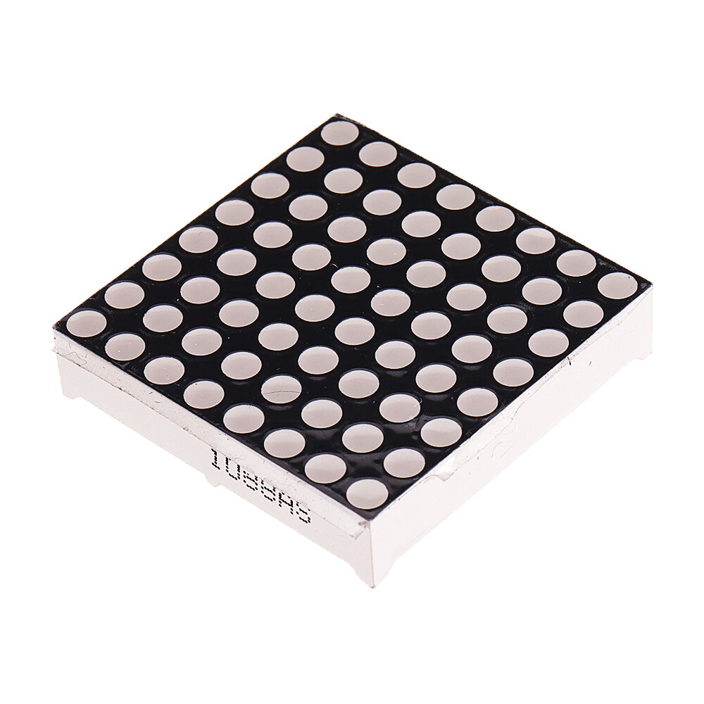
u00b7 A single module can drive an 8*8 common negative lattice
u00b7 Module operating voltage: 5V
u00b7 Module size: 3.2 cm long, 3.2 cm wide and 1.5 cm high
u00b7 With 4 fixed screw holes and 3 mm diameter, it can be fixed with M3 copper column.
u00b7 Modules with input and output interfaces support multiple modules cascade
Wiring instructions:
The left side of the module is the input port, and the right side is the output port.
When controlling a single module, you only need to connect the input port to the CPU.
When multiple modules are cascaded, the input end of the first module connects to the CPU, the output end connects to the input end of the second module, the output end of the second module connects to the input end of the third module, and so on.
Take 51 single chip computer as an example:
u00b7 VCC 5V
u00b7 GND GND
u00b7 DIN_P20
u00b7 CS_P21
u00b7 CLK_P22
Package included:
10 x MAX7219 Dot Matrix Module DIY kit
Products related to this item
Loading related products...
❮
❯
Videos for similar product
Loading product videos...
❮
❯
Electronics Ranking


